Sensor Control
This section covers the configuration and initialisation of DMPACK for sensor data collection. Basic knowledge of
regular expressions and familiarity with the Lua syntax are recommended. The sensor control examples are written for
Linux and assume DMPACK to be installed to /opt. The path /opt/bin must be added to the global
PATH variable.
Humidity Sensor
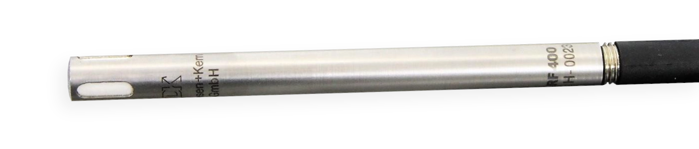
The DKRF400 is a temperature and humidity probe made by Driesen + Kern GmbH. The standard probe DKRF400 is calibrated for the temperatures range –40 .. +80 °C, with an accuracy of ±0.3 °C at 25 °C. The probe is suitable for the range of 0 .. 100 % relative humidity and has an accuracy of ±1.8 % in the range of 20 .. 80 %. The sensor returns the following measured parameters:
temperature [°C],
relative humidity [%],
absolute humidity [g/m³],
dew point [°C],
wet-bulb temperature [°C].
The sensor is available with analog and digital output signals (RS-232, USB, RS-485). This section is based on the
digital version with RS-232 interface. Use an USB serial adapter if the sensor node does not provide a distinct COM
port. By default, the digital DKRF400 starts sending values over the serial line once the sensor is connected to the
host. We can change from stream to request/response mode through a basic ASCII protocol: the command s\r
stops the continuous output of reponses and the command Meter\r returns a single response (\r
is carriage return).
Serial interface specifications of the DKRF400 sensor:
| Name | DKRF400 |
| Manufacturer | Driesen + Kern GmbH |
| Interface | RS-232 |
| Protocol | ASCII |
| Connector | D-sub (DE-9) |
| Baud rate | 9600 |
| Byte size | 8 |
| Parity | none |
| Stop bits | 2 |
| DTR | enabled |
| RTS | enabled |
The serial connection can be tested with minicom(1).
$ sudo apt-get install minicomIn this case, the first COM port is mapped to device /dev/ttyS0. The user under which
minicom(1) runs must be member of group dialout to access the device. The command-line argument
-s is passed to display the setup menu at start:
$ minicom -sSelect Serial port setup to change the TTY parameters to 9600 baud and 8N2. Return and select Exit to receive sensor responses:
Welcome to minicom 2.8

OPTIONS: I18n
Port /dev/ttyS0, 20:56:16

Press CTRL-A Z for help on special keys

-MTAA-DKrF400
Enhanced Architecture HW.V. 4.0
SW.V. 4.12 build Sep 28 2010 13:49:50C 530 166
(c) Driesen+Kern GmbH Bad Bramstedt Germany
SNr: XXXXX
Range:     -40'C   ..       80'C               0%    ..      100%
status: 0840    08      00      00      01      00      80      25      01
Vref: 2500.000000
SHT1X7X
   26.84 'C        53.03 %         13.52 g/m3      16.46 'C        19.97 'C
   26.84 'C        53.03 %         13.52 g/m3      16.46 'C        19.97 'C
   26.84 'C        52.97 %         13.51 g/m3      16.44 'C        19.96 'C
The key combination CTRL + A O shows the options menu again, and
CTRL + A X exits minicom(1).
Databases
Use dminit to create the observation and the log database in directory
/opt/var/dmpack/:
$ cd /opt/var/dmpack/
$ dminit --database observ.db --type observ --wal
$ dminit --database log.db --type log --wal
Create node node-1, sensor dkrf400, and target target-1 in database
observ.db through dmdbctl:
$ dmdbctl -d observ.db -C node --id node-1 --name "Node 1"
$ dmdbctl -d observ.db -C sensor --id dkrf400 --name "DKRF400" --node node-1
$ dmdbctl -d observ.db -C target --id target-1 --name "Target 1"
Configuration
On request Meter\r, the sensor returns an ASCII response containing temperature, relative humidity,
absolute humidity, dew point, and wet-bulb temperature:
21.90 'C \t 57.60 % \t 11.11 g/m3\t 13.16 'C \t 16.50 'C \t\rThe tab character 0x09 and the carriage return 0x0d in the raw response of the sensor will
be replaced by dmserial with \t and \r respectively. The program also
extracts the values from the raw response and adds them to the entries in the pre-defined responses list if a regular
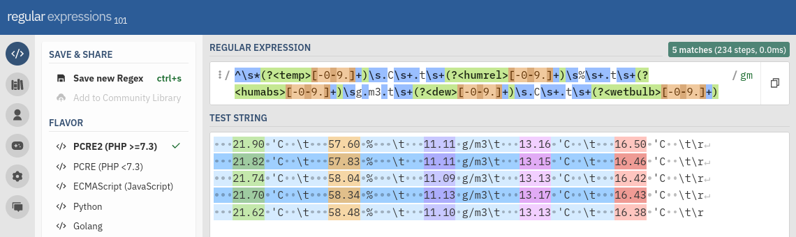
expression pattern has been set. The following pattern was made with the online tool regex101.com (Creating the regular expression pattern of the
DKRF400 response with) and matches the sensor responses of the DKRF400:
^\s*(?<temp>[-0-9.]+)\s.C\s+.t\s+(?<humrel>[-0-9.]+)\s%\s+.t\s+(?<humabs>[-0-9.]+)\sg.m3.t\s+(?<dew>[-0-9.]+)\s.C\s+.t\s+(?<wetbulb>[-0-9.]+)The group names temp, humrel, humabs, dew, and
wetbulb within the pattern must match the names given in the responses list. The name length is limited to
32 characters. Optionally, the responses can be given a unit in attribute unit and a response type in attribute type. If no response type is
set, RESPONSE_TYPE_REAL64 (double precision number) is assumed by default.
In the configuration file, each backslash character \ has to be escaped with an additional
\. Simply replace every occurance of \ with \\:
^\\s*(?<temp>[-0-9.]+)\\s.C\\s+.t\\s+(?<humrel>[-0-9.]+)\\s%\\s+.t\\s+(?<humabs>[-0-9.]+)\\sg.m3.t\\s+(?<dew>[-0-9.]+)\\s.C\\s+.t\\s+(?<wetbulb>[-0-9.]+)Set the regular expression pattern as value of attribute pattern in request get_values of
observation meter. The complete configuration file of dmserial is listed below.
-- dmserial.conf

-- Global variables of identifiers used in the configuration. The values must
-- match the records added to the database.
node_id   = "node-1"
sensor_id = "dkrf400"
target_id = "target-1"

-- Observations to be used in jobs list.

-- Start the sensor by sending a single carriage return.
start = {
  name = "start",         -- Observation name (required).
  target_id = target_id,  -- Target id (required).
  request = "\\r",        -- Raw request to send to sensor.
  delimiter = "\\n",      -- Response delimiter.
  pattern = "",           -- RegEx pattern of the response.
  delay = 500,            -- Delay in msec to wait afterwards.
  receiver = ""           -- Observation receiver.
}

-- Stop "Meter Mode". The sensor response will be ignored if no delimiter is
-- set (as the DKRF400 does not always return a response to the command).
mode = {
  name = "mode",          -- Observation name (required).
  target_id = target_id,  -- Target id (required).
  request = "s\\r",       -- Raw request to send to sensor.
  delimiter = "",         -- Response delimiter.
  pattern = "",           -- RegEx pattern of the response.
  delay = 500,            -- Delay in msec to wait afterwards.
  receiver = ""           -- Observation receiver.
}

-- Perform single measurement.
meter = {
  name = "meter",         -- Observation name (required).
  target_id = target_id,  -- Target id (required).
  request = "Meter\\r",   -- Raw request to send to sensor.
  delimiter = "\\r",      -- Response delimiter.
  pattern = "^\\s*(?<temp>[-0-9.]+)\\s.C\\s+.t\\s+(?<humrel>[-0-9.]+)\\s%\\s+.t\\s+(?<humabs>[-0-9.]+)\\sg.m3.t\\s+(?<dew>[-0-9.]+)\\s.C\\s+.t\\s+(?<wetbulb>[-0-9.]+)",
  delay = 0,              -- Delay in msec to wait afterwards.
  receiver = "dmdb",      -- Observation receiver.
  responses = {
    -- List of expected responses (up to 64).
    { name = "temp",    unit = "degC" }, -- Temperature (real64).
    { name = "humrel",  unit = "%"    }, -- Relative humidity (real64).
    { name = "humabs",  unit = "g/m3" }, -- Absolute humidity (real64).
    { name = "dew",     unit = "degC" }, -- Dew point (real64).
    { name = "wetbulb", unit = "degC" }  -- Wet-bulb temperature (real64).
  }
}

-- Settings of program dmserial. Change the name to the parameter given through
-- command-line argument `--name`.
dmserial = {
  logger = "dmlogger",   -- Name of logger instance (implies log forwarding).
  node = node_id,        -- Sensor node id (required).
  sensor = sensor_id,    -- Sensor id (required).
  output = "",           -- Path of optional output file, or `-` for stdout.
  format = "",           -- Output file format (`csv`, `jsonl`).
  path = "/dev/ttyS0",   -- TTY device path.
  baudrate = 9600,       -- TTY baud rate.
  bytesize = 8,          -- TTY byte size (5, 6, 7, 8).
  parity = "none",       -- TTY parity (`none`, `even`, `odd`).
  stopbits = 2,          -- TTY stop bits (1, 2).
  timeout = 5,           -- TTY timeout in seconds (max. 25).
  dtr = true,            -- TTY Data Terminal Ready (DTR) enabled.
  rts = true,            -- TTY Request To Send (RTS) enabled.
  jobs = {               -- List of jobs to perform.
    {
      -- (1) Start sensor.
      disabled = false,  -- Skip job.
      onetime = true,    -- Run job only once.
      group = { start }, -- Observations to perform.
      delay = 2000       -- Delay in msec to wait afterwards.
    }, {
      -- (2) Stop "Meter Mode".
      disabled = false,  -- Skip job.
      onetime = true,    -- Run job only once.
      group = { mode },  -- Observations to perform.
      delay = 2000       -- Delay in msec to wait afterwards.
    }, {
      -- (3) Measure values.
      disabled = false,  -- Skip job.
      onetime = false,   -- Run job only once.
      group = { meter }, -- Observations to perform.
      delay = 300 * 1000 -- Delay in msec to wait afterwards.
    }
  },
  debug = false,         -- Forward debug messages to logger.
  verbose = false        -- Output debug messages to console.
}
Save the configuration to /opt/etc/dmpack/dmserial.conf.
Monitoring
Start the dmlogger process first:
$ dmlogger --node node-1 --database /opt/var/dmpack/log.db --verboseThen, start the dmdb database process:
$ dmdb --logger dmlogger --node node-1 --database /opt/var/dmpack/observ.db --verboseFinally, start dmserial to execute the configured jobs:
$ dmserial --config /opt/etc/dmpack/dmserial.conf --verboseTemperature Sensor
1-Wire is a half-duplex serial bus designed by Dallas Semiconductor that is typically used to communicate with low-cost digital thermometers and weather stations. This section describes the configuration of DMPACK programs to retrieve temperature values from a single 1-Wire sensor. The following hardware is required:
1-Wire temperature sensor,
1-Wire USB adapter iButtonLink LinkUSB.
Make sure that USB power saving is disabled or the LinkUSB adapter may be detached after a while. The sensor data is read with dmfs and stored to database with dmdb. Additionally, the dmlogger program will capture log messages. The sensor has to be mounted through the virtual 1-Wire File System (OWFS).
1-Wire File System
The 1-Wire File System provides an abstraction layer to access the measurement values of attached sensors. An additional driver is required to mount the virtual file system to which sensors are mapped. On Linux, simply install the OWFS package:
$ sudo apt-get install owfsThen, connect the temperature sensor via the USB adapter. The device path may be /dev/ttyUSB0 or
/dev/ttyU0 depending on the operating system, and will differ if an RS-232 adapter is used instead. Mount
the file system with owfs(1) under /mnt/1wire/:
$ sudo mkdir -p /mnt/1wire
$ sudo owfs -C -d /dev/ttyUSB0 --allow_other -m /mnt/1wire
The command-line argument -C selects output in °C. The settings can be added to the owfs(1)
configuration file /etc/owfs.conf:
device = /dev/ttyUSB0
mountpoint = /mnt/1wire
allow_other
Celsius
The file system is mounted automatically at system start-up if owfs(1) is configured to run as a service. Read a temperature value from the connected sensor:
$ cat /mnt/1wire/10.DCA98C020800/temperature
19.12
The name of the virtual directory 10.DCA98C020800 depends on the sensor id.
Databases
Once the file system is configured, initialise the observation and log databases with dminit:
$ cd /opt/var/dmpack/
$ dminit --database observ.db --type observ --wal
$ dminit --database log.db --type log --wal
Create node node-1, sensor owfs, and target target-1 in database
observ.db through dmdbctl:
$ dmdbctl -d observ.db -C node --id node-1 --name "Node 1"
$ dmdbctl -d observ.db -C sensor --id owfs --name "OWFS" --node node-1
$ dmdbctl -d observ.db -C target --id target-1 --name "Target 1"
Configuration
The DMPACK program dmfs will read temperature values periodically from the OWFS and forward
observations to dmdb to be saved in the database. Copy the following dmfs
configuration to /opt/etc/dmpack/dmfs.conf:
-- dmfs.conf
-- Global identifiers and sensor file path used in the configuration. The
-- identifiers must match the records in the database.
node_id   = "node-1"
sensor_id = "owfs"
target_id = "target-1"
file_path = "/mnt/1wire/10.DCA98C020800/temperature"

get_temp = {
  name = "get_temp",                -- Observation name (required).
  target_id = target_id,            -- Target id (required).
  request = file_path,              -- File path.
  pattern = "(?<temp>[-+0-9\\.]+)", -- RegEx pattern of the response.
  delay = 500,                      -- Delay in msec to wait afterwards.
  receiver = "dmdb",                -- Observation receiver.
  responses = {
    {
      name = "temp",                -- RegEx group name (max. 32 characters).
      unit = "degC",                -- Response unit (max. 8 characters).
      type = RESPONSE_TYPE_REAL64   -- Response value type.
    }
  }
}

dmfs = {
  logger = "dmlogger",      -- Logger to send logs to.
  node = node_id,           -- Node id (required).
  sensor = sensor_id,       -- Sensor id (required).
  output = "",              -- Path of optional output file, or `-` for stdout.
  format = "none",          -- Output file format (`csv` or `jsonl`).
  jobs = {
    -- List of jobs to perform.
    {
      disabled = false,     -- Skip job.
      onetime = false,      -- Run job only once.
      group = { get_temp }, -- Observation to execute (required).
      delay = 10 * 1000,    -- Delay in msec to wait afterwards.
    }
  },
  debug = false,            -- Forward logs of level DEBUG via IPC.
  verbose = true            -- Print messages to standard error.
}
The path /mnt/1wire/10.DCA98C020800/temperature in variable file_path must match the actual
file system path of the sensor. The job will be performed every 10 seconds and repeated indefinitely. Log messages are
sent to the dmlogger process of default name dmlogger, and observations to the
dmdb process of default name dmdb.
Monitoring
Start the dmlogger process first:
$ dmlogger --node node-1 --database /opt/var/dmpack/log.db --verboseThen, start the dmdb database process:
$ dmdb --logger dmlogger --node node-1 --database /opt/var/dmpack/observ.db --verboseFinally, start dmfs to execute the configured job:
$ dmfs --config /opt/etc/dmpack/dmfs.confUV Sensor
The UV-Cosine is a waterproof and dirt-repellent UV sensor by sglux GmbH, with analog (4–20 mA, 0–5 V, 0–10 V) or digital (USB, Modbus RTU, CAN) output. Depending on the model, the spectral sensitivity of the sensor is calibrated for broadband UV, UVA, UVB+C, UVC, UV index, bluelight, or UV+VI.
For this section, the digital model with Modbus interface and broadband UV sensitivity is used. See the official Programming Manual on how to program the UV-Cosine. The sensor uses non-standard Modbus holding register addresses:
| Address | Name | Type | Bytes | Access | Description |
|---|---|---|---|---|---|
| 100 | hardware revision | uint16 |
2 | RD | hardware revision number |
| 101 | firmware revision | uint16 |
2 | RD | firmware revision number |
| 104 | serial number | uint32 |
4 | RD | sensor serial number |
| 106 | sensor address | uint16 |
2 | RDWR | Modbus slave id |
| 107 | sensor protocol | uint16 |
2 | RDWR | baud rate, parity, stop bits |
| 110 | product vendor | string16 |
16 | RD | vendor name (SGLUX GMBH) |
| 118 | product name | string16 |
16 | RD | product name |
| 126 | sensor name | string16 |
16 | RDWR | user-defined device name |
| 1030 | calibration date | uint32 |
4 | RD | date of calibration |
| 1032 | calibration 1 | string16 |
16 | RD | name of calibration 1 |
| 1040 | calibration 2 | string16 |
16 | RD | name of calibration 2 (or ?) |
| 1048 | calibration 3 | string16 |
16 | RD | name of calibration 3 (or ?) |
| 1056 | calibration 4 | string16 |
16 | RD | name of calibration 4 (or ?) |
| 1064 | calibration 5 | string16 |
16 | RD | name of calibration 5 (or ?) |
| 2000 | cycle count | uint16 |
2 | RD | measurement cycle counter |
| 2001 | status | uint16 |
2 | RD | status of ADC |
| 2002 | timestamp | uint32 |
4 | RD | internal timestamp [msec] |
| 2004 | radiation 1 | float |
4 | RD | radiation by calibration 1 [W/m²] |
| 2006 | radiation 2 | float |
4 | RD | radiation by calibration 2 [W/m²] |
| 2008 | radiation 3 | float |
4 | RD | radiation by calibration 3 [W/m²] |
| 2010 | radiation 4 | float |
4 | RD | radiation by calibration 4 [W/m²] |
| 2012 | radiation 5 | float |
4 | RD | radiation by calibration 5 [W/m²] |
| 2014 | temperature | float |
4 | RD | internal sensor temperature [°C] |
The radiation in W/m² (calibration factor 1) is read from register 2004 and the internal temperature in
°C from register 2014, both as floating-point number in ABCD byte order. We can test the register access
with dmmbctl and output the UV radiation. If the sensor is connected through an USB adapter on
/dev/ttyUSB0, run:
$ dmmbctl --path /dev/ttyUSB0 --baudrate 115200 --bytesize 8 --parity even --stopbits 1 \
  --slave 1 --read 2004 --type float --order abcd
1.87749458
The RS-485 interface parameters may be configured through register 107 (hi-byte/lo-byte combination).
The factory default is 0x2606 for 115200 baud (8E1). Set the register to 0x0606 (1542) for
115200 baud (8N1):
$ dmmbctl --path /dev/ttyUSB0 --baudrate 115200 --bytesize 8 --parity even --stopbits 1 \
  --type uint16 --write 107 --slave 1 --value 1542
Change the slave id to 2 by writing to register 106:
$ dmmbctl --path /dev/ttyUSB0 --baudrate 115200 --bytesize 8 --parity even --stopbits 1 \
  --type uint16 --write 106 --slave 1 --value 2
Finally, write 0xFF01 (65281) to hidden register 10 and then disconnect the sensor from
power for the changes to take effect:
$ dmmbctl --path /dev/ttyUSB0 --baudrate 115200 --bytesize 8 --parity even --stopbits 1 \
  --type uint16 --write 10 --slave 1 --value 65281
Once reconnected, the sensor is configured to 115200 baud (8N1) and Modbus slave id 2:
$ dmmbctl --path /dev/ttyUSB0 --baudrate 115200 --bytesize 8 --parity none --stopbits 1 \
  --slave 2 --read 2004 --type float --order abcd
1.87591026
Configuration
The Modbus monitoring program dmmb will read radiation and internal temperature from the sensor. The
observations are written to /tmp/timeseries.jsonl in JSONL format, without any database storage for
simplicity. Copy the dmdb configuration to /opt/etc/dmpack/dmmb.conf:
-- dmmb.conf

get_radiation = {
  name = "get_radiation",
  target_id = "target-1",
  receiver = "",
  request = "access=read, slave=2, address=2004, type=float, order=abcd",
  responses = {{ name = "radiation", unit = "W/m2" }}
}

get_internal_temperature = {
  name = "get_internal_temperature",
  target_id = "target-1",
  receiver = "",
  request = "access=read, slave=2, address=2014, type=float, order=abcd",
  responses = {{ name = "temperature", unit = "degC" }}
}

dmmb = {
  logger = "",
  node = "node-1",
  sensor = "uv-cosine",
  output = "/tmp/timeseries.jsonl",
  format = "jsonl",
  mode = "rtu",
  rtu = {
    path = "/dev/ttyUSB0",
    baudrate = 115200,
    bytesize = 8,
    parity = "none",
    stopbits = 1
  },
  tcp = {
    address = "127.0.0.1",
    port = 502
  },
  jobs = {
    {
      disabled = false,
      onetime = false,
      delay = 10 * 1000,
      group = {
        get_radiation,
        get_internal_temperature
      }
    }
  },
  debug = false,
  verbose = false
}
Monitoring
Start dmmb to write the measurement values to file /tmp/timeseries.jsonl:
$ dmmb --name dmmb --config /opt/etc/dmpack/dmmb.conf --verboseWatch the output file:
$ tail -f /tmp/timeseries.jsonlWeather Station
This section describes the set-up of DMPACK programs to capture sensor data of the digital weather station WSC11 by Adolf Thies GmbH & Co KG. The model used in this example is connected through Modbus RTU to the sensor node. The input registers will be read by the Modbus control program dmmb. All observations are forwarded to dmdb for database storage.
The weather station is offered with RS-485 (ASCII, Modbus RTU) or KNX interface. Depending on the hardware model, the following values are measured:
wind speed and direction;
global radiation, twilight, and brightness (north, east, south, west);
precipitation status, intensity (option) and amount (option);
ice/frost/snow detection (option);
temperature and dew point;
absolute and relative humidity;
absolute air pressure and air pressure at sea level (QNH);
sun position, elevation, azimuth;
longitude, latitude, and elevation;
date and time.
The WSC11 has its RS-485 interface factory-set to 9600 baud (8N1) and its Modbus slave id to 1. In order to change
the baud rate, the default password (234) has to be written to register 40009 first:
$ dmmbctl --path /dev/ttyUSB0 --baudrate 9600 --bytesize 8 --parity none --stopbits 1 \
  --type uint32 --write 40009 --slave 1 --value 234
For 115200 baud, write parameter 9 to register 40005:
$ dmmbctl --path /dev/ttyUSB0 --baudrate 9600 --bytesize 8 --parity none --stopbits 1 \
  --type uint32 --write 40005 --slave 1 --value 9
The sensor is now reconfigured.
Databases
In order to store any observations or logs, initialise the databases with dminit first:
$ cd /opt/var/dmpack/
$ dminit --database observ.db --type observ --wal
$ dminit --database log.db --type log --wal
Create node node-1, sensor thies-wsc11, and target target-1 in database
observ.db through dmdbctl:
$ dmdbctl -d observ.db -C node --id node-1 --name "Node 1"
$ dmdbctl -d observ.db -C sensor --id thies-wsc11 --name "Thies WSC11" --node node-1
$ dmdbctl -d observ.db -C target --id target-1 --name "Target 1"
Optionally, set the sensor type to meteo (for meteorological sensors) with argument --type.
Alternatively, the entities can be added with dmweb instead.
Configuration
In this example, the weather station is connected via a WaveShare RS-232/RS-485/TTL converter on
/dev/ttyUSB0. The Modbus connection may be tested with dmmbctl first. For instance, read
input register 34601 to output the current date in format YYYYMMDD:
$ dmmbctl --path /dev/ttyUSB0 --baudrate 115200 --bytesize 8 --parity none --stopbits 1 \
  --slave 1 --read 34601 --type uint32
20250305
As each observation may contain a maximum of eight requests, reading the input registers is split into multiple
observations. Unwanted measurement jobs can simply be disabled. See the user manual (PDF) for an overview of all Modbus
registers. The register values are automatically scaled and converted to response type
RESPONSE_TYPE_REAL64. The last job does not contain an observation and only causes the program to wait for
60 seconds before the next cycle starts.
The target and the receiver of all observations are declared globally at the top of the file. Copy the
dmmb configuration to /opt/etc/dmpack/dmmb.conf if DMPACK is installed to
/opt:
-- dmmb.conf
target_id = "target-1"
receiver = "dmdb"

--
-- Observation groups for Thies WSC11 weather station.
--

-- Get wind speed and direction.
get_wind = {
  {
    name = "get_wind_speed",
    target_id = target_id,
    receiver = receiver,
    request = "access=read, slave=1, address=30001, type=uint32, scale=10",
    responses = {{ name = "wind_speed", unit = "m/s" }}
  }, {
    name = "get_wind_speed_avg",
    target_id = target_id,
    receiver = receiver,
    request = "access=read, slave=1, address=30003, type=uint32, scale=10",
    responses = {{ name = "wind_speed_avg", unit = "m/s" }}
  }, {
    name = "get_wind_dir",
    target_id = target_id,
    receiver = receiver,
    request = "access=read, slave=1, address=30201, type=uint32, scale=10",
    responses = {{ name = "wind_dir", unit = "deg" }}
  }, {
    name = "get_wind_dir_avg",
    target_id = target_id,
    receiver = receiver,
    request = "access=read, slave=1, address=30203, type=uint32, scale=10",
    responses = {{ name = "wind_dir_avg", unit = "deg" }}
  }
}

-- Get temperature, humidity, and air pressure.
get_temp_hum_press = {
  {
    name = "get_temperature",
    target_id = target_id,
    receiver = receiver,
    request = "access=read, slave=1, address=30401, type=int32, scale=10",
    responses = {{ name = "temperature", unit = "degC" }}
  }, {
    name = "get_internal_temperature",
    target_id = target_id,
    receiver = receiver,
    request = "access=read, slave=1, address=30403, type=int32, scale=10",
    responses = {{ name = "internal_temperature", unit = "degC" }}
  }, {
    name = "get_relative_humidity",
    target_id = target_id,
    receiver = receiver,
    request = "access=read, slave=1, address=30601, type=uint32, scale=10",
    responses = {{ name = "rel_humidity", unit = "%rh" }}
  }, {
    name = "get_absolute_humidity",
    target_id = target_id,
    receiver = receiver,
    request = "access=read, slave=1, address=30603, type=uint32, scale=100",
    responses = {{ name = "abs_humidity", unit = "g/m3" }}
  }, {
    name = "get_dew_point",
    target_id = target_id,
    receiver = receiver,
    request = "access=read, slave=1, address=30605, type=int32, scale=10",
    responses = {{ name = "dew_point", unit = "degC" }}
  }, {
    name = "get_absolute_pressure",
    target_id = target_id,
    receiver = receiver,
    request = "access=read, slave=1, address=30801, type=uint32, scale=100",
    responses = {{ name = "abs_pressure", unit = "hPa" }}
  }, {
    name = "get_relative_pressure",
    target_id = target_id,
    receiver = receiver,
    request = "access=read, slave=1, address=30803, type=uint32, scale=100",
    responses = {{ name = "rel_pressure", unit = "hPa" }}
  }
}

-- Get global radiation, brightness, and sun position.
get_radiation = {
  {
    name = "get_global_radiation",
    target_id = target_id,
    receiver = receiver,
    request = "access=read, slave=1, address=31001, type=int32, scale=10",
    responses = {{ name = "radiation", unit = "W/m2" }}
  }, {
    name = "get_brightness_north",
    target_id = target_id,
    receiver = receiver,
    request = "access=read, slave=1, address=31201, type=uint32, scale=10",
    responses = {{ name = "bright_north", unit = "kLux" }}
  }, {
    name = "get_brightness_east",
    target_id = target_id,
    receiver = receiver,
    request = "access=read, slave=1, address=31203, type=uint32, scale=10",
    responses = {{ name = "bright_east", unit = "kLux" }}
  }, {
    name = "get_brightness_south",
    target_id = target_id,
    receiver = receiver,
    request = "access=read, slave=1, address=31205, type=uint32, scale=10",
    responses = {{ name = "bright_south", unit = "kLux" }}
  }, {
    name = "get_brightness_west",
    target_id = target_id,
    receiver = receiver,
    request = "access=read, slave=1, address=31207, type=uint32, scale=10",
    responses = {{ name = "bright_west", unit = "kLux" }}
  }, {
    name = "get_twilight",
    target_id = target_id,
    receiver = receiver,
    request = "access=read, slave=1, address=31209, type=uint32, scale=1",
    responses = {{ name = "twilight", unit = "Lux" }}
  }, {
    name = "get_sun_elevation",
    target_id = target_id,
    receiver = receiver,
    request = "access=read, slave=1, address=34805, type=int32, scale=10",
    responses = {{ name = "sun_elevation", unit = "deg" }}
  }, {
    name = "get_sun_azimuth",
    target_id = target_id,
    receiver = receiver,
    request = "access=read, slave=1, address=34807, type=int32, scale=10",
    responses = {{ name = "sun_azimuth", unit = "deg" }}
  }
}

-- Get GPS position (longitude, latitude, elevation in NN/NHN).
get_position = {
  {
    name = "get_longitude",
    target_id = target_id,
    receiver = receiver,
    request = "access=read, slave=1, address=34801, type=int32, scale=1000000",
    responses = {{ name = "longitude", unit = "deg" }}
  }, {
    name = "get_latitude",
    target_id = target_id,
    receiver = receiver,
    request = "access=read, slave=1, address=34803, type=int32, scale=1000000",
    responses = {{ name = "latitude", unit = "deg" }}
  }, {
    name = "get_elevation_nn",
    target_id = target_id,
    receiver = receiver,
    request = "access=read, slave=1, address=34809, type=uint32, scale=1",
    responses = {{ name = "elevation_nn", unit = "m" }}
  }, {
    name = "get_elevation_nhn",
    target_id = target_id,
    receiver = receiver,
    request = "access=read, slave=1, address=34817, type=uint32, scale=10",
    responses = {{ name = "elevation_nhn", unit = "m" }}
  }
}

dmmb = {
  logger = "dmlogger",
  node = "node-1",
  sensor = "thies-wsc11",
  output = "",
  format = "",
  mode = "rtu",
  rtu = {
    path = "/dev/ttyUSB0",
    baudrate = 115200,
    bytesize = 8,
    parity = "none",
    stopbits = 1
  },
  tcp = {
    address = "127.0.0.1",
    port = 502
  },
  jobs = {
    {
      disabled = false,
      onetime = false,
      delay = 60 * 1000,
      group = {
        get_wind,
        get_temp_hum_press,
        get_radiation,
        get_position,
      }
    }
  },
  debug = false,
  verbose = false
}
Monitoring
Start the dmlogger process to store any logs:
$ dmlogger --node node-1 --database /opt/var/dmpack/log.db --verboseStart the dmdb database process to store the observations:
$ dmdb --logger dmlogger --node node-1 --database /opt/var/dmpack/observ.db --verboseStart dmmb to execute the configured jobs:
$ dmmb --name dmmb --config /opt/etc/dmpack/dmmb.conf --verboseDigital Multimeter
Digital multimeters are used to measure values like voltage, resistance, current, and temperature. If equipped with a serial interface, modern devices are even programmable through protocols like SCPI.
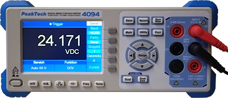
In this example, the voltage of a 24 VDC power supply unit is monitored using a PeakTech 4094 graphical bench
multimeter. The multimeter features an RS-232 interface and SCPI protocol support. The voltage values will be read by
dmserial, forwarded to dmrecv, and displayed as a trend graph without additional
persistence. The serial port is configured to the default parameters of the device (115200 baud, 8N1). The 50 VDC
measurement function has to be selected using the keys on the front panel or via the SCPI command
SENSe:FUNCtion. See the official
programming manual (PDF) for an overview of supported SCPI commands.
The captured voltage is filtered by GNU awk first and then rendered with trend. On Linux, install the required packages first:
$ sudo apt-get install gawk trendConfiguration
The multimeter is attached to /dev/ttyUSB0. The sensor control program dmserial will
send the measurement command MEAS1? once every second to the PeakTech 4094 to read the voltage, then
forward the observation to dmrecv for plotting. Values are usually returned in scientific notation.
Therefore, the regular expression pattern for response extraction has to include the character E.
-- dmserial.conf

get_voltage = {
  name = "get_voltage",                -- Request name (required).
  target_id = "target-1",              -- Target id (required).
  request = "MEAS1?\\r\\n",            -- Raw request to send to sensor.
  delimiter = "\\r\\n",                -- Response delimiter.
  pattern = "^(?<voltage>[-+.0-9E]+)", -- RegEx pattern of the response.
  delay = 0,                           -- Delay in msec to wait afterwards.
  receiver = "dmrecv",                 -- Observation receiver.
  responses = {                        -- List of expected responses.
    {
      name = "voltage",                -- RegEx group name (max. 32 characters).
      unit = "VDC",                    -- Response unit (max. 8 characters).
      type = RESPONSE_TYPE_REAL64      -- Response value type.
    }
  }
}

dmserial = {
  logger = "",                -- Name of logger instance (implies log forwarding).
  node = "node-1",            -- Sensor node id (required).
  sensor = "peaktech-4094",   -- Sensor id (required).
  output = "",                -- Path of optional output file, or `-` for stdout.
  format = "",                -- Output file format (`csv`, `jsonl`).
  path = "/dev/ttyUSB0",      -- TTY device path.
  baudrate = 115200,          -- TTY baud rate.
  bytesize = 8,               -- TTY byte size (5, 6, 7, 8).
  parity = "none",            -- TTY parity (`none`, `even`, `odd`).
  stopbits = 1,               -- TTY stop bits (1, 2).
  timeout = 0,                -- TTY timeout in seconds (max. 25).
  dtr = false,                -- TTY Data Terminal Ready (DTR) enabled.
  rts = false,                -- TTY Request To Send (RTS) enabled.
  jobs = {                    -- List of jobs to perform.
    {
      disabled = false,       -- Skip job.
      onetime = false,        -- Run job only once.
      group = { get_voltage}, -- Observation group to execute.
      delay = 1000            -- Delay in msec to wait afterwards.
    }
  },
  debug = false,              -- Forward logs of level DEBUG via IPC.
  verbose = false             -- Print messages to standard error.
}
Additionally, we can add a job to select the measurement function via SCPI before starting observation
meter (for instance, AC/DC voltage, AC/DC current, frequency, or resistance).
Monitoring
Start dmserial and pass the path to the configuration file as a command-line argument:
$ dmserial --name dmserial --config config/dmserial.conf --verboseThe program dmrecv will print responses of name voltage in ASCII block format to
standard output. gawk(1) then extracts the response value and pipes it to trend(1):
$ dmrecv --name dmrecv --type observ --format block --response voltage \
  | gawk '{ print $2 | "trend - 60" }'
The trend graph is rendered in real-time with OpenGL.